POLAR MOUNTS FOR EME DISHES by W4OP

Perhaps the most daunting part of assembling an EME station for 23cM and up is the mechanical aspects of moving the dish. Many of us are very capable of building cavities, preamps, even feedhorns, but motors, gear boxes and chains have little to do with electronics.


The Options


Two methods of pointing an antenna at the moon are in use: azimuth/elevation and polar (also called equatorial). By far azimuth/elevation is the more common of the two. It is easy to envision AZ/EL pointing. The azimuth motor rotates the dish to different compass directions just like a traditional yagi antenna rotor. The elevation motor, then, raises the antenna from the horizon to perhaps as high as straight up into space. Before the days of computers, calculating AZ/EL coordinates was a complex task, and depending on the size of the array, or dish, coordinates would have to be calculated for perhaps as often as every minute.


I once had an engineering professor that told us the easiest way to solve a complex problem was to first convert the problem to the proper coordinate system. Celestial objects like planets, stars and moons move in circular arcs and therefore are best treated with a spherical coordinate system. Mounts that accommodate this type of movement are known as polar mounts because their axis of rotation is parallel to earth’s axis of rotation. Once calibrated, only one motor is required to track an object- and perhaps best of all, the mount will rotate at a constant, or linear rate. So, right off, we have reduced all the mechanics and electronics required by a factor of 2. Manual tracking is also simplified as we now only have to be concerned with updating one drive instead of 2. Finally, we will see that you can purchase off the shelf polar mounts and controllers inexpensively.


Lunar Mechanics


Even if you have no interest in polar mounts for moon tracking, a knowledge of how the moon moves through the sky in spherical coordinates will give you a better understanding and feeling for why the moon rises and sets at different times and at different positions along the horizon.


To begin with we need to familiarize ourselves with three terms: Greenwich Hour Angle  (GHA),  Local Hour Angle (LHA) and Declination.


Declination


At 
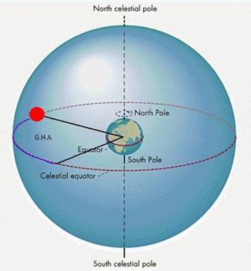
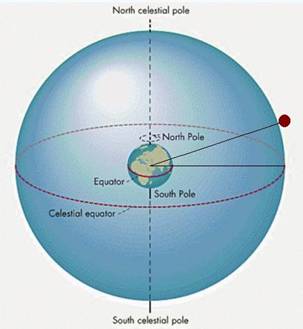
the left, we have placed a plane through the earth at its equator- the imaginary plane extends infinitely into space and is called the celestial equator. During its 28 day cycle, the moon’s orbit appears to move above and below the celestial equator. The amount of this movement changes over periods of years, and is known as declination. Currently it is around +/- 24 degrees.

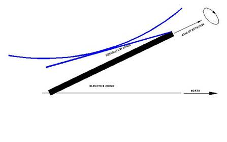
       When the moon’s orbit is above the celestial equator (as seen in the northern hemisphere) the declination is positive, zero when on the equator and negative when below the equator.  The higher the moon’s declination, the longer it will be above the horizon (visible) in the northern hemisphere. This is one of the reasons that activity weekends are planned for not only perigee (moon’s closest approach to the earth), but also high declination; as there is a longer EU-USA window.


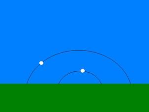
Here we illustrate the moon’s path at a high and a low declination. By way of comparison, at my QTH SSW of Asheville, NC, the moon is visible for over 14 ½ hours at high declination, and only 9 ½ hours at low declination. The apparent motion of celestial objects across our sky is primarily due to the rotation of the earth. Given that the earth rotates once on its axis each day, we can easily see that celestial objects (sun, stars, planets) appear to move at a rate of 360/24= 15 degrees/hour.


GHA and LHA


Just as we passed an imaginary plane through the earth’s equator and into space, let’s pass a 2nd plane through Greenwich England and perpendicular to the equator.


A celestial object that is intersected by this plane is said to be at 0 GHA (Greenwich Hour Angle). And will appear overhead.  One hour later, that same object will be at 15 GHA, 2 hours at 30 GHA etc.


Let’s say you live near New York City. This is about 75 degrees west longitude.  5 hours (75/15=5) after the object was over Greenwich it will appear directly over New York City and would then be said to be at 75 GHA.


Let’s introduce another convenient definition- Local Hour Angle (LHA). To convert GHA to LHA, one simply subtracts their longitude. Using our example, someone in NY (75 W Long.) would see the moon directly overhead when it was at 75 GHA or 0 LHA.  Similarly, the moon rises at approximately –90 LHA and sets at +90 LHA. It turns out that the moon rises and sets at exactly -90 and +90 LHA only when the declination is zero- but the approximation is always close and gives the operator an immediate feel for how far across the sky the moon has progressed.


In summary, we may think of declination as celestial latitude and hour angle as celestial longitude.


In the case of the moon we need to recall that it is also orbiting the earth once every 28 days. In addition, this lunar orbiting is in the same direction as the earth is rotating. The effect is to slow the apparent motion of the moon through the sky.  To see by how much we need only divide 1 day (earth rotation period) by 28 days (lunar orbital period), and then divide again by 24 hours and subtract this amount from the 15 degrees/hour. The result is an apparent lunar motion of 14.5 degrees/hour, or about ½ degree slower than the sun. Thus, the moon is always falling behind the sun by ½ degree/hour. In one day this results in the moon rising about 50  minutes later each day. This is the primary cause of the phases of the moon. If this is not yet clear, imagine the extreme case; an object in the sky that orbits the earth, in the same direction as the earth rotates, once each day.  Such an object would appear stationary to an earth based observer. This is the orbital characteristic of geostationary satellites. 


Tracking the Moon

Look again at this figure, and concentrate on the moon at 0 declination (on the celestial equator).

Now, imagine you are sitting in a kind of chair on the equator.


The chair has been modified so its back is parallel to the axis of rotation of the earth, and that the back of the chair is attached to a motor that rotates 14.5 degrees per hour (or just under one revolution/day. To an observer sitting in this chair, the moon would appear stationary in the sky. This is precisely what we require in a mount to track the moon.

Similar mounts are used in astronomy to track celestial objects and are referred to as equatorial or polar mounts.


With a bit of modification, the moon need not be at 0 declination and the mount need not be located on the equator.


A polar mount has three adjustments that will allow it to track the moon (or sun) from anywhere on earth:


  1. The elevation adjust is set to your latitude
  2. The azimuth angle is set to true north

  3. The declination is set to that of the object to be tracked.


Note that once steps 1 and 2 have been accomplished, the axis of rotation of the mount is now parallel to that of the earth’s.  Also note that the rate of declination change for the moon is a very slow function. Once this is set on the polar mount it is good for perhaps 12 hours or more without need for further adjustment.


A Practical EME Polar Mount

Most of us are probably familiar with the mounts and drive systems that were in use for C band satellite systems. These were polar mounts, most often moved by a linear actuator.

These mounts may be adapted directly for EME, with three drawbacks:


  1. The degree of travel is generally only about 110 degrees. Close to 180 degrees would be necessary to allow access to the moon on both horizons.
  2. The declination range is quite limited- generally only a few degrees plus declination and perhaps 10 degrees of minus declination. In addition, since this adjustment was made to be set just once, it may not be convenient for continual resetting.
  3. The degree of mount movement per inch of actuator travel is not linear- this could be overcome probably by a lookup table in firmware or just a chart.


Of more use to us are the horizon to horizon mounts. As their name implies, they are capable of a full 180 degrees of movement and the degree of travel is linear or constant. These were less common probably because they were more expensive.


The mount we will discuss was one originally made by Ajak Industries. I have bought several of these from TVRO dealers for $25 each. New they sold for about $300 retail.

Unfortunately, Ajak stopped making this drive when the C band market dried up. The good news is that virtually the same mount may be purchased new from KTI in Wisconsin.


The Modifications

The original declination adjustment was accomplished by placing two ½” bolts into different sets of holes in the mount. This yields a very narrow range of declination and must be modified. The original mount and ring are shown in the photos in the next frame.


The photographs in this frame show how the ring and mount are modified to allow for variable declination (click each one to enlarge). My mount now allows for +28 degrees to –11 degrees declination. Because the vast majority of EME activity occurs at high declination, the lack of full negative declination is not an issue.


Top: Illustrates the hinge arrangement on the north end of the mount. Two ears were welded to the ring with ½” holes in them.  A steel tube with ½” I.D. and a length equal to the inside distance between the ears is welded to the motor drive. A ½” bolt then pins these two together allowing the ring to pivot.


Middle: Illustrates the south hinge, swivel and threaded rod used to set the declination.


Bottom: View from west side of the mount showing overall drive and shelf bracket for the digital level.


These photos show the original mount and ring (click to enlarge)

     Photo 6                 Photo 7            Photo 8              Photo 9


Photograph 6: Mounting ring before modification.


Photograph 7: Close up view of the north end of ring before hinge modification.


Photograph 8: Close up of south end of motor drive.


Photograph 9: View of North end of motor drive.


Setting Declination

Setting the declination angle can be accomplished in a number of ways. Look again at the drawing to the right. The declination angle either adds to the elevation angle (negative dec.) or subtracts from it (positive dec).


To change the declination, refer to Photo 4, below. The hex nuts on the threaded rod are moved up or down until the proper angle is obtained.


In the bottom picture, the round inclinometer is available from hardware stores and the digital level can be bought on the internet. The inclinometer is magnetically attached to the dish ring- so with the dish at zenith it reads the elevation angle +/- declination. If the moon is at +10 degrees declination, and the mount is set for my QTH (latitude=35=elevation angle).

The declination adjustment will be moved until the inclinometer reads 35-10 = 25 degrees. The shelf that holds the digital level is offset by my latitude, so it reads the declination angle directly without having to do any subtraction or addition.


Controlling The Motor Drive

Once the polar mount is modified for variable declination, we need a way to run the motor and to determine how far the mount has moved.  The motor needs 12-20 VDC to run it. Although we could build a power supply to do this, there seems to be an endless supply of discarded TVRO dish controllers that are well suited to this. In addition to moving the mount, we need a way to keep track of how far it has moved. The Ajak and KTI mounts contain a magnet wheel and reed switch. Each time a magnet passes by the reed switch, it will close and then reopen. KTI indicates their mount yields 10 counts per degree of travel. My Ajak mount is 9.2 counts per degree.  The TVRO dish controllers will accept the reed switch output from the drive and display the movement as a 3 or 4 digit count on the front panel.


Of all the controllers I have looked at, the Houston Tracker IV is best suited to this task. It contains an easy to read blue plasma display that shows a 4 digit count, is easily programmed for east and west limits of rotation and can store up to 70 dish positions. These memories can be handy when performing sun noise or system temperature measurements


Another useful feature of the HT IV is that many came outfitted with a UHF remote control. This makes it very easy to rotate the dish while working at the dish site- the controller can remain in the shack. The controller is well built on fibreglass PC boards, the micro and EPROM are socketed and schematics are available.


This controller was very popular. One seems to show up on Ebay every month or more often, going for $20-$30. I have also seen them at ham fests, as cheap as $1!

I  built my sequencer onto the bottom of the controller, borrowing power from the Tracker and using spare terminals on the rear apron for connections to the P.A., transceiver, LNA etc.


Tracking The Moon


The last item we need to take care of is relating dish movement to moon location. All of the tracking programs I looked at calculated polar mount data in addition to AZ/EL coordinates, but the VK3UM EME Planner by Doug MacArthur is best suited for polar mounts as it also computes L.H.A.  Recall that when the moon is at zenith, LHA= 0.


After many E-Mail discussions with Doug about how he could expand the polar capabilities of his program, we came up with the following system.


The dish is rotated to 0 L.H.A. (straight up). This is easily verified with a level placed across the mount ring. A memory clear is done on the Houston Tracker IV- this presets the count to 5000. Moving the dish east decrements the count; west movement increments the count.   Doug then wrote software that yields a counter on his display page that is also preset to 5000 when the moon is at local zenith. Function F10 allows the user to enter the counts/degree of his particular system.  Once this number is entered, the 4 digit number in the upper left continually updates. With dishes up to 18’ or so, all  the operator has to do is press the west button on the Houston Tracker every 5 minutes or so to make the number on the Houston Tracker display coincide with the number on the computer display. That’s all there is to it. Fig. 6 shows a typical screen from EME Tracker. The 4 digit counter is in the upper left along with the counts/degree readout.


Screen Capture of  VK3UM EME Planner


Because the rate of rotation of the moon is linear and constant (14.5 degrees/hour) and the

Pulse output of the polar mount is linear and constant (10 counts/degree) the individual well versed in PIC programming could probably easily make a controller that could automatically track the moon.


Summary


We have shown that TVRO polar mounts can be purchased new or surplus and readily modified for lunar tracking.  This drastically reduces the hardware normally required to track the moon when compared with more traditional AZ/EL systems. TVRO dish controllers are readily available for controlling the motor and the VK3UM EME Planner has been modified to uniquely interface with these controllers.


Return to Welcome page