| The A2 encoder
can be used for azimuth or elevation with suitable
gearing, but it is easier to use the
A2T encoder
for elevation because it is an inclinometer (works via
gravity rather than being driven by a shaft).
To order these parts you must work up the part number by combining the options you want. The web page gives all the particulars. We do recommend the sealed housings to help keep out moisture. For the Azimuth encoder we recommend the A2-S-B-D-M-S. The part number was derived as follows: Series = A2, S = SEI buss, B = Ball Bearing, D = Default shaft extension, M = Includes mounting plate, S = Sealed Housing. For the inclinometer the part number is A2T-S-D-S. Series = A2T, S = SEI buss, D = Double Damping, S = Sealed housing. When you buy A2 encoders, you can order wires with connectors in the length you need (US Digital part CA-MD6-SH-MD6-XX. The connector on the wire kit will plug directly into J1. If you are using the absolute encoders for both azimuth and elevation then you will need 3 of the wires and a 'Y' adaptor Note 1.
Alternatively you can buy wire, connectors and a crimp tool for RJ11 connectors and make up the wiring yourself. You will still need the Y adaptor if you are using two A2 encoders. Note 1: US Digital does not seem to carry the Y adaptors any more. Maybe they do but not on their web pages. I found some on Amazon, but could not link the page here. Be very careful when ordering, the part must be specified as 6P6C for six wire connectors. Most Y adaptors on the market are for 4 pins and will not work for the absolute encoders. |
 The 'Y' combines the signals
from each of the encoders. You will need to determine the
needed length for each side of the 'Y' as well as the
length of the main line.
The 'Y' combines the signals
from each of the encoders. You will need to determine the
needed length for each side of the 'Y' as well as the
length of the main line.| The part numbers are ETS25 or MAB25. The MAB25 is a
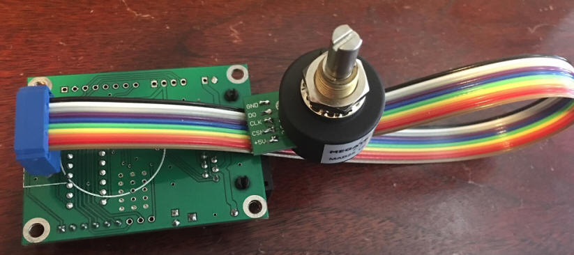
discontinued item, but will work well if you find some. The part number to order is ETS25 6x22 05SER LA. They are about $50 each. The 6x22 indicates the shaft size (6.35 by 22 mm), 05SER indicates it is a 5 volt part and has a serial interface (do not order the ones that they advertize as an absolute interface), and LA indicates that the connection to the device is solder pads.
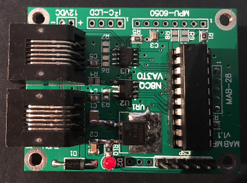
The designation for the adaptor board is MABMPU and can be ordered from Gary, N8CQ, Here are photos of the front and back of the board. The two RJ11 connectors are connected in parallel, so if you have two absolute encoders you can route them through and the board becomes the Y adaptor. Plus 12 VDC is applied to the board from the Drz Control CT-2 board, via the RJ11 Jack. The board has it's own 5 volt regulator for the encoder. As with the US Digital encoders, you can make your own cables or order wires with connectors in the length you need (US Digital part CA-MD6-SH-MD6-XX.
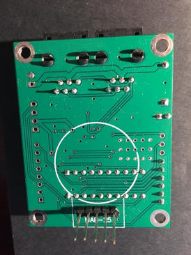
This is the bottom of the board. If desired you can mount the ET25 encoder directly on the board by sliding the pins through the through holes on the connection pads on the encoder. The bottom of the encoder will sit where the white circle is. This is a good arrangement if you are able to house the board and the encoder in the same location. Below is a photo of another way to make the connection. In this case I was putting the encoder directly in a Yaesu G800 rotator, replacing the potentiometer. There was not room inside the rotator for the board so I used a short length of flat wire to go from the encoder to the existing G800 connector, then about 4 feet of normal rotator cable from the rotator to my relay box on the tower, where the MabMpu board is housed. A US Digital inclinometer is installed above the G800 and it's cable runs down past the G800 and into the same box, where it plugs into the MabMpu board. Then the main encoder cable runs from the MabMpu board, down to the shack and connects to the Drz CT-2 controller. This works fine, but for any longer run I suspect that twisted pair wiring would be needed between the rotator and the MabMpu board.
|
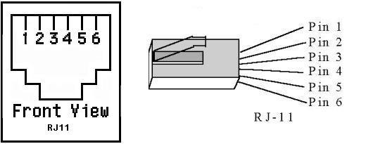
J1 - RJ11 - Input for A2 Absolute Encoders