Z-Index configuration
This page shows how to assemble and wire the LS485-IDX board.  
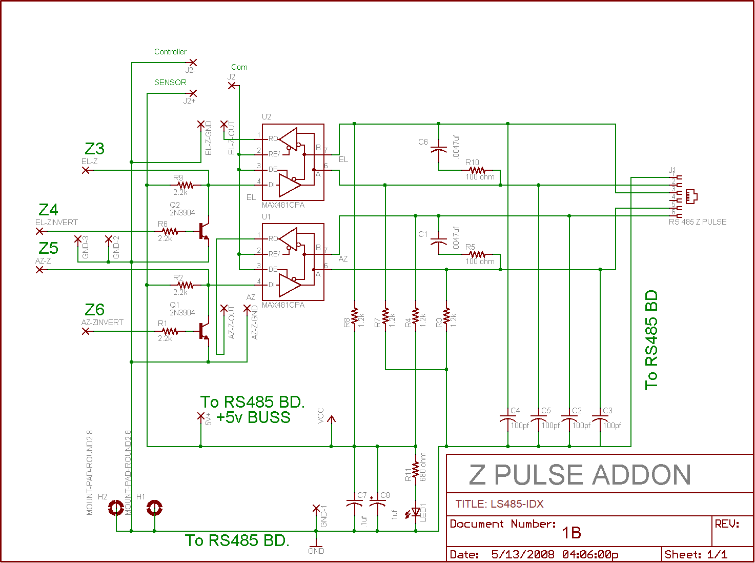
The board is used to convert TTL level index pulses from an incremental encoder to RS485 level signals to be transmitted to the CT-2 controller. For index operation you will need to order one LS485-1 and one LS-485-IDX boards.

Below you will find the following sections:

System connection diagram
Mounting
Wiring
Theory of operation
Schematic


System Connection Diagram


The LS485-IDX is a LS-485-1 with an index board attached.  This combination is only needed at the encoder (antenna) end of the system.  See below for details and wiring information.


 LS485-IDX Board Pair

The photos above show the mounting for the LS485-IDX board.  This combination of boards is used at the encoder (antenna) end of the data lines.  (The Index board is not used at the controller end of the data line.)  The encoders connect to the J4 and J5 connections on the LS485-1  board, except for the index pulse wires which connect to the pads on the right of the IDX board.  Two lines carrying RS485 signals are run to the CT-2 controller board.  The RJ45 connector on the LS485-1 board outputs the differential position signals while the RJ11 connector on the LS485-IDX board outputs the differential index pulses.

At the the CT-2 end of the lines, the RJ11 connector plugs directly into the jack on the CT-2, while the RJ45 line plugs into a second RS485 board that is configured as a line receiver.  The output of that board is also via an RJ45 connector and a short CAT-5 jumper is used to connect to the CT-2 board.


LS485-IDX Wiring

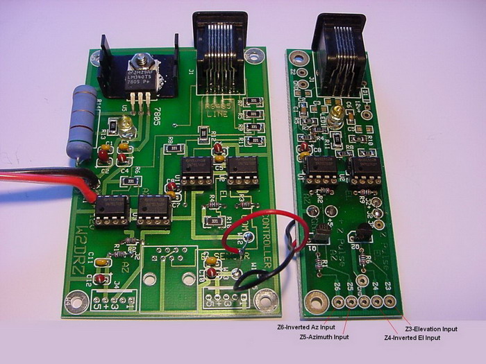
This picture shows the connections between the LS485-IDX (left) and the LS485-1 boards.  The red and black jumper wires are +5 volts and ground (supplying the index board).  The connections from the encoders for position data connect to the pads labeled J4 and J5 on the LS485-1 board as detailed in the RJ45 page.  The index pulse leads from the encoders go to the pads on the LS485-IDX board as shown above.

Note the +12v and ground (red and black) wires connecting to the LS485-1 board (at left above).  A long CAT5 cable run will not have enough current capability to supply the LS-485 boards. So when the LS485-1 board is used at the encoder end of the line it must be supplied with a local source of +12 to +14 volts.  If this power supply is remote from the board, be sure to use heavy enough wire so that the voltage at the LS485-1 is at least +12 volts.  The regulator on the LS485-1 board has enough current capacity to supply the +5 volts to the index board.
 

Wiring for J1, the RJ11 Jack
Pin 1 Ground Pair #1
Pin 2 Elevation index Pair #2
Pin 3 Elevation index Pair #2
Pin 4 No connection Not necessary to connect at either end
Pin 5 Azimuth index Pair #3
Pin 6 Azimuth index Pair #3


Use cable with 3 twisted pairs between the LS485-IDX and the CT-2 boards. The table at the left shows the usage of each pair of wires, and the pins to connect.  You can order this cable pre-made from US Digital.  Specify part number CA-MD6-SH-MD6-XX, where XX is the length desired up to 500 feet.  This is shielded cable.


Index Pulse Operation
Incremental encoders that provide an index (or zero) pulse output a short data pulse each time the encoder shaft passes the index position, once per revolution.  This pulse is normally a TTL level voltage, zero volts when not at index, +5 volts at index position.  It is necessary to provide isolation and immunity from noise, RF pickup, and potential damage to the encoder and the CT-2 board electronics.  Also TTL level signals are difficult to detect reliably over long lines.  So it is necessary to convert the TTL data from the encoder to RS-485 level signals for transmission to the CT-2 board.  The LS485-IDX board provides this level conversion, noise immunity, and isolation.  Here is how it works:

The index pulse from the encoder is connected to either the elevation or the azimuth channel on the LS485-IDX board.  Both channels work the same way, so only azimuth will be described here.  The encoder index pulse is wired to the Z5 pad on the IDX board, the azimuth channel.  The pulse goes to pin 4 of U1, a MAX481 line driver chip. The output of U1 is on pins 6 and 7.  These are complimentary outputs, pin 7 being the inverse of pin 6.

The differential signal from pins 6 and 7 are fed to pins 5 and 6 of J1, the RJ11 connector where they are transmitted down the twisted pair line to the CT-2 board's RJ11 connector.

At the CT-2 board the differential index pulses are connected to pins 6 and 7 of  IC4, another MAX481 chip.  The MAX481 converts this signal back to a single TTL level pulse that is then delivered to the CPU at pin 6 (RA4).  This TTL signal is the same in timing and sense as the original index pulse that was generated by the encoder.


Here is the schematic for the LS485-IDX board.