Incremental Encoders
Note: This is the hardware page for Incremental Encoders.  To find complete information on usage of these pulse type encoders, please refer to the Encoders page.

J2, the RJ45 connector is for incremental encoders that have differential outputs like those available from US Digital.  While it looks like it should work with any of their differential output encoders, we suggest the H6 and T6 series encoders.  You can also use the newer Slew Drives, as sold by W2HRO and others.

For both types of encoders, a level shifter device is needed to properly transmit the pulses from the encoders to the CT-2 Controller.  See Level Shifters for full details.


Using the Index Pulse
This capability is implemented in CT-2 controllers with version 2.1 or later firmware.  This pulse is called an index pulse, or Z-pulse (for Zero Pulse), or sometimes a Z-index.  Since the board was not originally designed for this, it is accomplished by using the RJ11 input jack that is normally used for absolute encoders.  Thus one cannot use absolute and z-index incremental encoders together.  An add-on board is available to handle converting the index pulse from TTL to RS485 levels at the encoder.  This is designated on our Products page as the LS485-IDX.  For wiring, and connection details see the links below.

  Our initial effort to provide index 
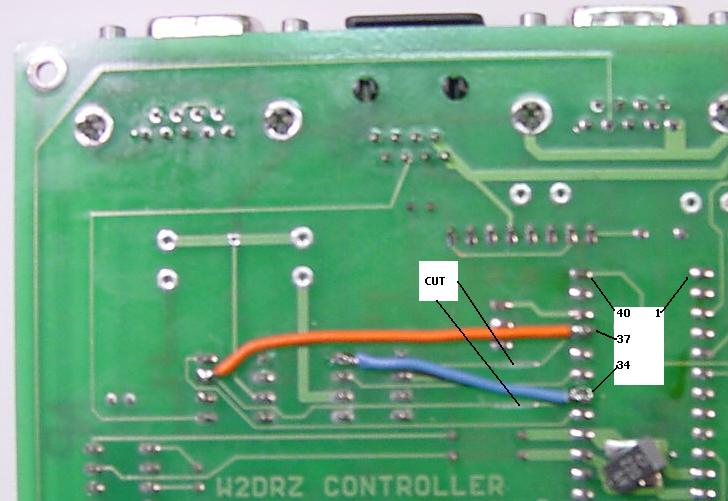
pulse detection did work for many encoders, but we soon discovered that there could be problems with some models, or when the encoders were mounted such as to provide reverse rotation from normal.  A change in software with a corresponding board modification cured that problem, see CT-2 Modifications for use with Index Pulse.

The CT-2 has been used with the following manufacturer's incremental encoders
US-Digital S5 and T5 Series - Note 1
BEI H25D Series - Note 2
Heidenhain Note 1
Dynapar Note 2

Note 1: The US Digital and Heidenhain encoders all produce a very short pulse each time the encoder shaft passes the zero point.  To work with these encoders, the jumpers at Pad1-Pad2 (for Azimuth), or at Pad3-Pad4 (for Elevation) must be removed.  Also see notes in the Reverse Gearing section, below.

Note2: The BEI and Dynapar encoders and some others produce a long pulse each time the encoder passes the zero point.  For these encoders the jumpers at Pad1-Pad2 and at Pad3-Pad4 must be connected.  Also see notes in the Reverse Gearing section, below.


Reverse Gearing
Incremental encoders are meant to be geared to the antenna so that the encoder shaft turns clockwise (as viewed from the top) when the antenna turns clockwise.  If your mounting arrangement requires that the encoder shaft turn counter-clockwise when the antenna turns clockwise then some special wiring is required.  Additionally it makes a difference whether you are using the index pulse or not.

If you are not using the index pulse, or if you are using US Digital or Heidenhain encoders, simply reversing the A and B leads from the encoder will allow the controller to count normally (positive for increasing azimuth or elevation).  This means reversing pins 3 and 5 on the wires from the encoder to the RS-485 board at the encoder. (See the LC485-1 board schematic and the connection table below the schematic.)

However for BEI and Dynapar encoders, simply reversing A and B will not work if you are also using the index pulse.  In that case do not reverse A and B as described above.  Instead it is necessary to change the connections in the RJ45 plug where it plugs into the RS-485 board at the controller.  The A channel connections must be reversed for azimuth or elevation (or both).  To accomplish this, for azimuth, reverse the wires to pins 3 and 6 at the RJ45 plug.  For elevation, reverse the wires to pins 7 and 8.  (See the LC485-1 board schematic.)


Specifying the US Digital H6 and T6 series Incremental Encoders
The H6 series encoder is suitable for azimuth or elevation encoding if driven by suitable gearing. The T6 series is easier to use for elevation as it is an inclinometer and will not require gearing (works via gravity rather than being driven by a shaft).

To order these parts you must work up the part number by combining the options you want. The web page gives all the particulars. A good part number for the Azimuth encoder is a H6-2500-I-S. The part number was derived as follows:

Series =H6, Counts per revolution = 2500, I = Produces Index pulse, S = Single Ended data output.  A good reason to select this unit is because it includes a mounting bracket.  Below is a picture of a similar unit mounted in a housing on the W2DRZ 16 foot dish.

For elevation we recommend the T6-2500-I-S-D inclinometer.  Counts per revolution = 2500, I = produces index pulse, S = Single Ended data output, D = Double Damping.  Double damping is important for an antenna controller as it will significantly reduce display 'jitter' during windy conditions or when starting/stopping the antenna.


CT-2 Modifications for Z-Pulse Operation
In order to support the Z-Pulse available with some incremental encoders, a modification to the CT-2 circuit board is required. All new CT-2 controllers incorporate the required board modifications, but if you have an older CT-2, or are upgrading your CT-1 to a CT-2. the modification is presented here.  Note that this modification is required if you have firmware version 2.10 or greater and you are using incremental encoders. (See the download page for information on finding the firmware version.)  The modification effectively swaps the function of the two microprocessor I/O lines called RB1 and RB4 (microprocessor pins 34 and 37).  The two existing traces to those pins must be cut and jumper wires to 'criss-cross' the connections must be soldered on.  The photo below shows the modification.


This photo shows the upper left corner of the bottom of the CT-2 board. The two traces shown must be cut, and the wires soldered on as shown.  The pins of the PIC microprocessor are shown for reference.

Back to Controller