| Our Level Shifter boards are to be used with incremental
encoders, to adjust levels being applied to the CT-2 Controller, and
to provide noise and radiation immunity to long data lines between
the encoders and the Controller board. Signals that change
between +5 volts and zero volts are called TTL level signals.
TTL stands for "Transistor-Transistor Logic", and is the term used
below and on other pages to describe the +5 volt signals that we
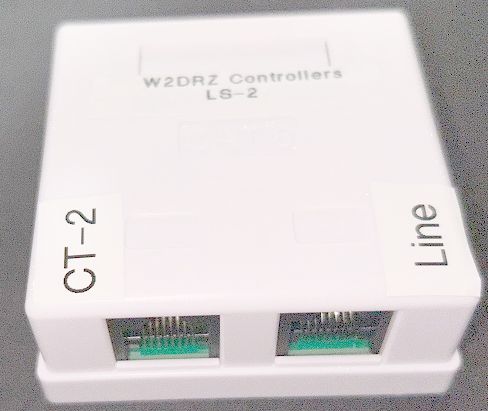
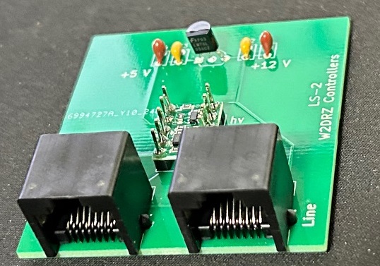
deal with. We sell two level shifter systems, the LS485-1 and the LS-2. Details on the LS-485 system are shown just below. Our LS-2 level shifter is designed to be used with the Slew drives sold by W2HRO and others. Click here for details on the LS-2 level shifter. Look on the Products page for price and ordering information for our Level Converters. |
|
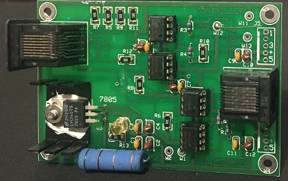
The US Digital, BEI, Heidenhain, Dynapar, etc, encoders all output TTL levels (5 volt pulses). For these encoders we recommend using our LS-485 level shifters. While the CT-2 controller can receive this TTL data directly, due to line length, noise pickup from relays, motors, etc, and strong RF fields, and for lightning protection, the data must be converted to some more robust format before being sent down the line to the controller board. A good way is to use RS485 level conversion. RS485 is more robust than RS232 and is recommended for longer lines and severe noise or RF environments. Once the converted signal reaches the vicinity of the controller board, it must be converted back to a TTL level before being applied to the board via J2. Here is the connection and wiring instructions for the LS-485-1 board. Two of these boards are required when using US Digital Incremental Encoders. They are used to convert the TTL signals from the encoders to RS-485 levels for transmission to the CT-1 controller. At the controller another LS-485-1 board is used to convert the RS-485 signals back to TTL level. The connection diagrams and schematic are shown below. This is a dual encoder board which can be configured for TTL to RS485 or for RS485 to TTL levels. Configuration is via a set of 3 jumper pads on the board. Jumper Pad W12 to Pad W13 for TTL to RS485 (using board at the encoder), or jumper Pad W12 to Pad W11 for RS485 to TTL levels (using board at the controller). The board has two sets of connections to wire to the incremental encoders. Use the J5 connections for the elevation encoder, and J4 for the azimuth encoder. For the board that connects directly to the controller, J2 connects to controller and J1 connects to the data line from the encoders. A wire jumper must be installed between the pads W12 and either W11 or W13, to configure the board to be at the encoder, or at the controller end of the line. When connecting the encoder data lines to the board, you connect data A to Pad3 and Data B to Pad5 on J4 and J5. Reverse if the direction needs to be reversed.
|