This page is linked from the Program Setup section of the detailed settings page. These options are for the drop box on the right hand side of the first tab in the Setup pages.
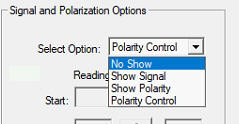
When set to "No Show" the field will not be shown. The other options are "Show Signal", "Show Polarity, and Polarity Control". If "Show Signal" or "Show Polarity" is selected the voltage display field will appear on the main dialog with the appropriate label.
Show Signal Option:
The Show Signal option allows display of a zero to +5 volt input value connected to pad 5 on the controller board (use pad6 for ground). This could be connected to the AGC output of a receiver, for instance, to show signal strength. It could also be used for any other analog voltage. Care must be used to ensure the voltage does not exceed +5 volts. Using a 7 volt Zener diode in parallel with the voltage input (between pad5 and pad6) is recommended. (If you use a 5 volt Zener the diode will start to conduct as the voltage approaches 5 volts, distorting the readings.)
Show Polarity Option:
The Show Polarity option is designed for a rotatable polarity antenna. The axis of rotation must be geared to a potentiometer that produces a 0 to +5 volt output over the range of rotation. That voltage must be connected to pad 5 on the controller board (using the same care as described above). Then, after calibration, the actual polarization of the antenna, in degrees, will be displayed on the main dialog. Note that this only displays the current polarization, it cannot control it.
When this option is selected, the lower portion of the window will be
populated with instructions for calibrating the display.
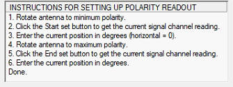
Here are the calibration controls:
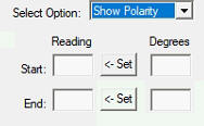
To calibrate, set the polarity to horizontal, enter zero degrees in the start degree field and then click the 'Set' button. The input voltage will be read and displayed in the 'Reading' field. Then rotate the polarity to 90 degrees, or whatever your end point will be, and enter that position into the End degree field. Then click the set button and get the reading for that position. Next click 'Apply' or 'Ok' to save the settings. Now the polarity in degrees will be shown on the main dialog.
The Polarity Control option is only available in DrzTrack version 5.21, and controller version 5.22, or later versions. It's purpose is to provide a way to switch an XY antenna, such as a crossed Yagi, between Horizontal and Vertical operation. It can also handle automatic polarity switching for receive or transmit intervals when operating digital EME modes with one minute transmit and receive sequences (such as JT65 and Q65).
When selected, the following window will be displayed in the
lower right portion of the main dialog:
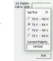
The 4 position 'radio' buttons show the possible usages. The first
two are used to manually switch the antenna for continuous horizontal,
or continuous vertical operation. The third position allows
automatic polarity switching, such that you will transmit on horizontal
and receive on vertical. The fourth option reverses the automatic
polarity operation.
The field at the bottom displays the current antenna polarity.
The Hardware Setup:
This option is designed to work with a pulsed relay that controls the antenna polarization. You pulse one line to switch to horizontal, and pulse a different line to switch to vertical. The relay must be wired so that the positive control voltage is always connected to the relay. The two minus coil connections are momentarily connected to ground (V-) to do the switching.
This is accomplished with the CT-2 by repurposing the speed control lines. These lines are available as pin 7 and 8 of the Male DB9, auxiliary connector. Pin 7 is used to pulse the vertical line, while pin 8 is used for horizontal. Note: If you are using hardware speed control from the CT-2 then you will not be able to use this H/V switching scheme.
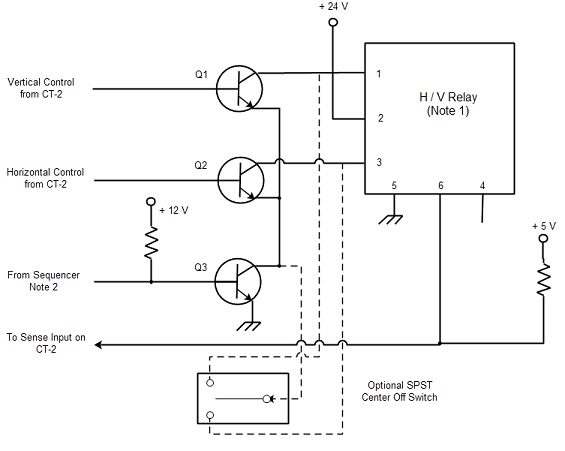
Here is a schematic of a possible H/V switching setup. The relay
is a Sector Microwave SM7N series coaxial switch (see pictures below).
The relay connections are:
1. Position 1 control, used for vertical plane. Momentary
ground to operate.
2.Common voltage connection. +24 volts.
3. Position 2 control, used for horizontal plane. Momentary ground
to operate.
4. Relay sense feedback for position 1 (not used).
5. Position sense ground connection.
6. Relay sense feedback for position 2. This is connected to
ground when in the horizontal position, thus removing voltage from the
sense line going to the CT-2 controller.
The display of the current polarization is accomplished by using the same voltage input line as described above for the signal and rotating polarization options (pad 5 on CT-2). The horizontal feedback line is connected so as to produce a low voltage when the antennas are horizontal, and a higher voltage (but not over 5 volts) when they are vertical. The CT-2 controller measures the voltage and displays the polarization according to the level seen.
The transistors Q1, Q2, and the safety transistor Q3 all handle the armature current of the relay. Since that is .9 amps, the 3 NPN transistors should all be able to handle at least 2 amps. They are all intermittent duty, so heat sinking them is not necessary.
The base connections to Q1 and Q2 come from the speed control lines of the CT-2 controller, pins 7 and 8 of the male DB9 connector.
Q3 is a safety transistor. It is used to prevent accidentally operating the relay while you are transmitting. It is tied to the first output of the sequencer, which goes to ground when transmitting, thus preventing the application of ground to Q1, Q2, and the optional, manual H/V switch. In this way, neither the operator or the computer can make the relays switch while RF power is applied. I forgot to label the resistors, the bias resistor connected to Q3 should be around 2-3k. The 5 volt pull up resistor on the sense line can be 5 to 10 k.
As shown on the schematic, you can also install a momentary contact SPDT switch to allow manual H/V switching. The way it is wired, you are still prevented from accidentally switching when transmitting. It is also possible to connect one or more LED indicators to the position sense feedback lines from the relay, to provide a quick visual indication of the current polarization.
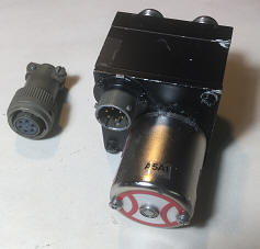
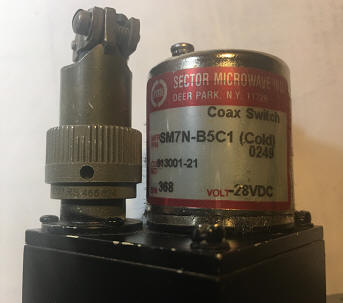
This is the relay that I used. These seem to be available on the surplus market, but I don't know where as I got mine from another local Ham. There are many other makes of relay that would work, but of course the wiring, voltage, current, could all be different. But the main thing that makes this system work well is that the relay is pulse operated and latching. To be absolutely clear; The CT-2 will not provide this function with non-latching relays.
Automatic Polarity Switching:
Ok, with the above hardware and circuitry you would now be able to click on the "TX H - RX H" or the "TX V - RX V" setting on the polarization control window and see that the relay will operate and do the switching. The next thing is to figure out the automatic switching in case the polarity is not the same for you and the station you are trying to work. This is handled in software by knowing what sequence you are transmitting on, and the current time. Currently switching is always done at the 55 second point in each minute. For example, suppose you have discovered that you need to transmit with vertical polarization, but receive with horizontal. You would click the "TX V - RX H" setting in the window, and make sure that the checkbox "TX First" is checked or not checked to match the same function in WSJT. Then if you are receiving and have the antenna already in horizontal, at second 55 of the minute the CT-2 will automatically generate the pulse to switch to vertical. Then, after your transmission has completed, again at the 55 second point, the CT-2 will switch you back to horizontal for your receive sequence.
That is all there is to it, but there a couple of issues. The first is that this was first developed for JT65 contacts. Switching at the 55 second point works well, even when sending a CW ID at the end of a sequence. However for Q65, the CW ID causes the transmitter to stay on beyond the 55 second point by a couple of seconds. I could change the code to switch at 58 seconds, but that only gives the operator 2 seconds after the switch to decide if he wants to make a change in polarity before transmitting. Of course this does not cause any harm to the equipment. Since the transmitter is still on the air at the 55 second point, even though the pulse is sent to the switching transistor, the safety transistor Q3 is still not conducting until the sequencer releases it - so the relay will not switch.
One possible fix is to not use the automatic CW ID, at least in Q65 mode. Also, I will probably add a function to adjust the switch point at some time in the future.
The second issue is that it is always necessary to check to make sure the TX First box in DrzTrack is set the same as in WSJT. If not, the automatic switching will work in reverse from what you want. I have tried to intercept messages from WSJT-X, to automatically adjust the TX First box, but while somewhat successful, it was not reliable, and so I have disabled that code for the time being. Perhaps I will find a reliable way to do this in the future.