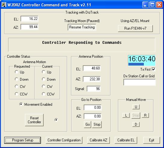
| The DrzTrack program is
used to set up the various parameters that are needed by
the controller, to test and calibrate the encoders, and to track the
Moon and Sun. It may also be used to
relay tracking information from other tracking programs to the controller.
It does this by communicating with the controller via the
serial port. Configuration data for the controller is
selected by the user and saved in the controller's
non-volatile memory so that once the configuration is
done, it does not have to be redone unless a change is
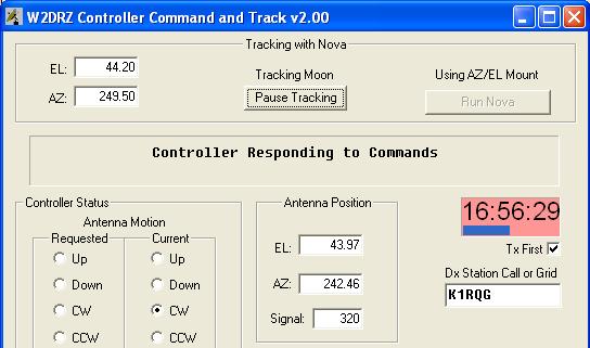
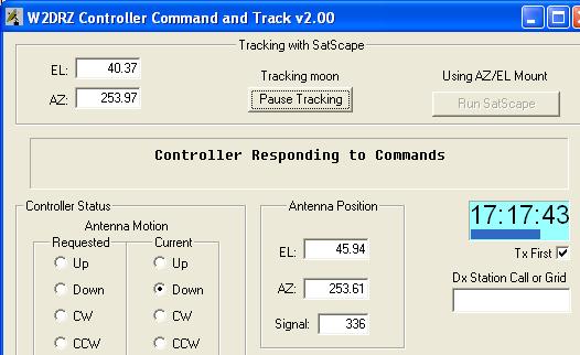
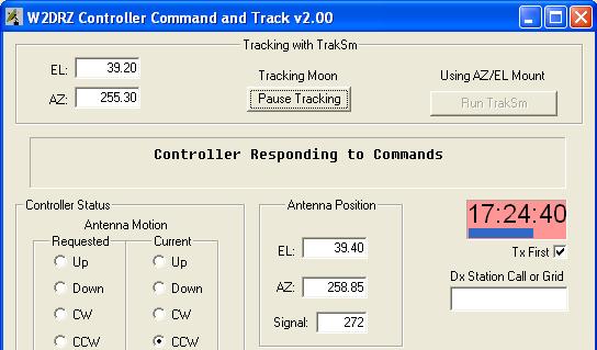
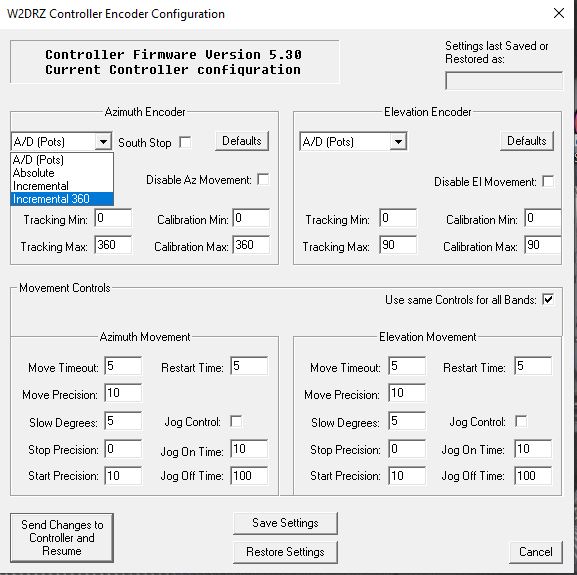
desired. When the DrzTrack program is started for the first time, it is necessary to set up the communications port and baud rate before it can communicate with the controller. Click on the "Program Setup" button and select the desired com port options. Click "OK" or "Apply" to save your settings. The program will remember your settings so you only have to do this once. The default rate that the CT-2 uses is 9600 baud. You can change this with the dip switches on the board, see Switch configuration and Setting for more details. Once the Comm port and baud rate are set, DrzTrack will start communicating with the controller. The status message (in bold print near the top) will change from "No Connection to Controller" to "Controller Responding to Commands", and the communications LED indicator will begin to flash. At this point no movement commands will be sent to the controller but it will try to display the current position and status of the controller board. Some of the status and communications indications will be operative as shown below, but they may not all work as the encoders have not yet been set up. Note that it is necessary for communication with the controller board to be working before the encoders can be configured. On a new controller, the default setting for encoder type is A/D for both Azimuth and Elevation. So if you are connected to some different kind of encoders, no position information can be displayed until you set up the encoders. However the little 'LED' next to the Reset button should be flashing at a rapid rate, indicating that serial communication with the controller has been established. Once communication is working, click on the "Encoder Configuration" button. The following window will appear:
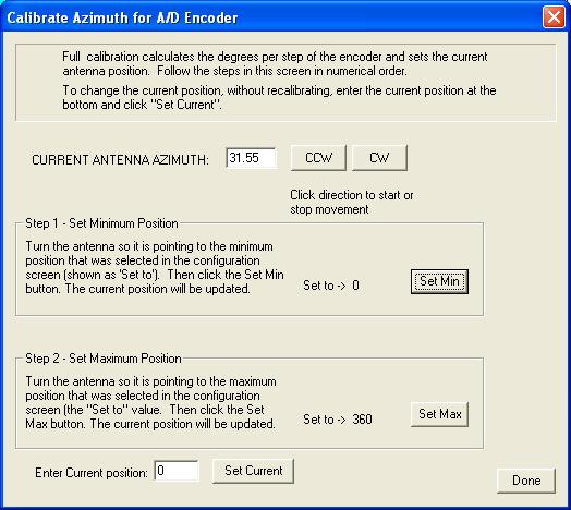
First select the correct encoder type for Azimuth and for Elevation, and set the appropriate ranges. Calibrate Min/Max should be set to the points you want to use when calibrating the controller. Tracking Min/Max set the limits that the antenna will traverse during tracking of heavenly bodies. The other settings are explained in detail in Detailed Settings. Once you have adjusted the settings click the 'Send Changes to Controller' button. The new settings will be sent to the controller board and stored in it's non-volatile memory, and the configuration window will be closed. You will return to the main program window communication with the controller will resume. (However after the controller receives a new configuration it will automatically 'reboot' so as to resume operation with the new settings. Thus it will take a few seconds before communication resumes.) |
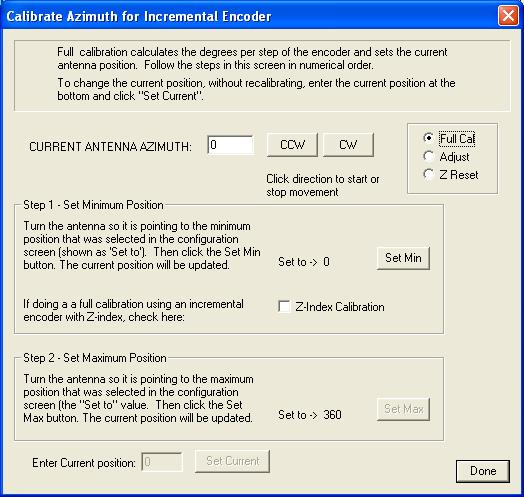
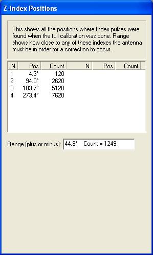 After
calibrating the antenna with Z-Indexes, and whenever entering the
incremental calibrate dialog when a Z-Index calibration has already been
done, a second dialog box will be shown along side of the calibrate
dialog shown above. This box shows the results of the Z-Index
counting and is shown to the left.
After
calibrating the antenna with Z-Indexes, and whenever entering the
incremental calibrate dialog when a Z-Index calibration has already been
done, a second dialog box will be shown along side of the calibrate
dialog shown above. This box shows the results of the Z-Index
counting and is shown to the left.