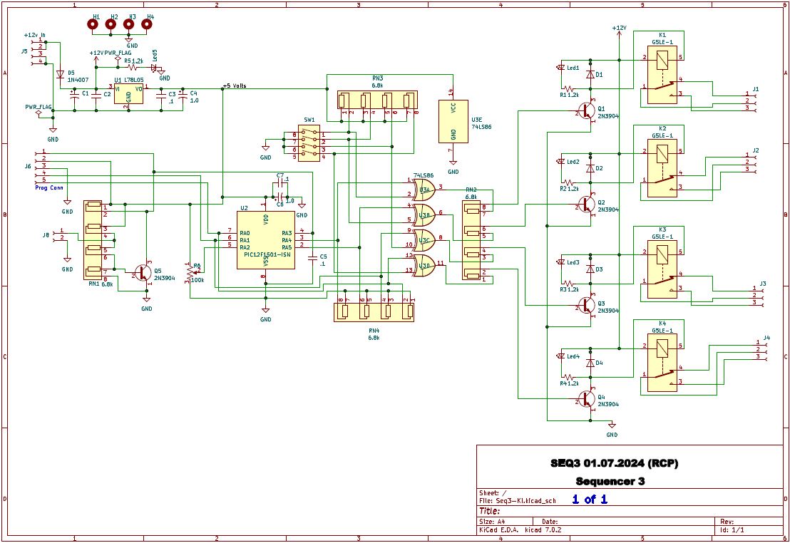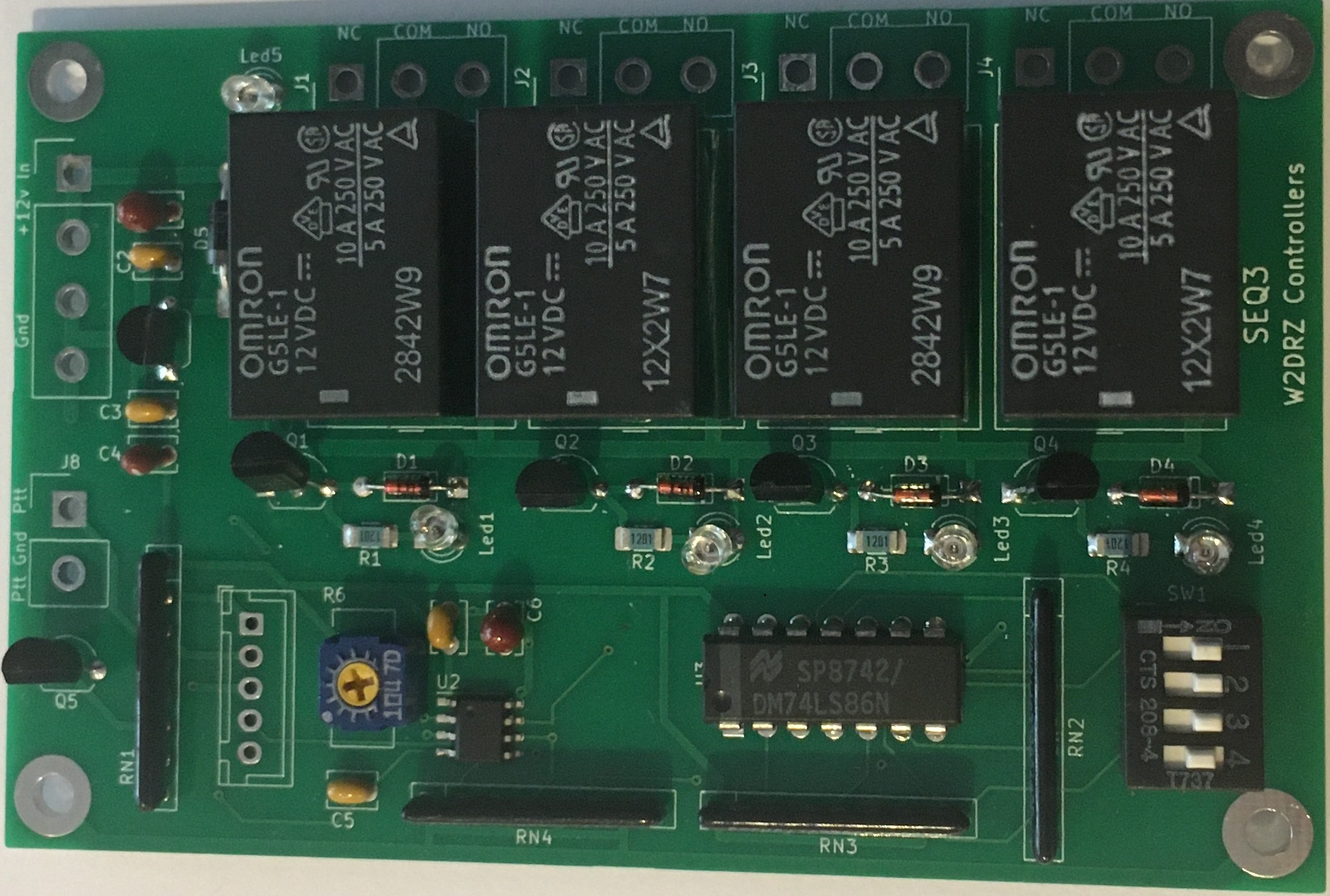
When the PTT input line is pulled to ground, the first relay K1 (connected to J1) switches, followed by K2, then K3 and finally K4. When releasing the PTT input from ground, the relays will de-activate in the reverse order. If, at any time the PTT input is changed in mid sequence, the sequence will automatically reverse, giving the same sequence delay for all changes.
Normally K1 will be connected to your antenna relay. K4 will enable the application of RF power to the antenna, whether by turning on the final amplifier, or enabling a transmit inhibit on your radio. K2 and K3 can provide turn on of intermediate amplifiers as needed for your system. You may want to read my article on sequencing if you are new to using a sequencer. See Sequencing for VHF Stations
The potentiometer labeled R6 is the sequence speed control. Turn it clockwise to increase the time delay between each relay activation. The range is from almost instantaneous to about 1/2 second for each sequence. You want to make sure it is slow enough to allow every relay to be activated, or deactivated during it's own sequence. Normally a delay of 100 to 200 milliseconds will be satisfactory. Faster if you are sure you have fast relays.
A good way to wire external relays (antenna relay and others) is to always have power to the plus side of the relay and bring the negative sides to the sequencer, where they will be grounded when the sequencer relays activate. Thus you can connect the common sequencer outputs to ground and the negative leads from your relays to the NO (normally open) sequencer output.
IMPORTANT NOTE: Do not forget to use protection diodes on all your external relays! Without the diodes, the reverse EMF from turning those relays off can damage your equipment, including the relays in the sequencer.